OpenCV 4.13.0
Open Source Computer Vision
読み込み中...
検索中...
見つかりません
🤖 AIによる機械翻訳(非公式) — これは OpenCV 4.13.0 公式リファレンス(英語)を AI (Claude) で自動翻訳したものです。訳に誤りを含む場合があります。正確な情報は 公式英語版(原文) を参照してください。
テクスチャ付き物体のリアルタイム姿勢推定

前のチュートリアル: OpenCVによるカメラキャリブレーション
次のチュートリアル: インタラクティブなカメラキャリブレーションアプリケーション

原著者Edgar Riba
互換性OpenCV >= 3.0

今日では、拡張現実(AR)はコンピュータビジョンやロボティクス分野における最先端の研究テーマの一つである。拡張現実における最も基本的な問題は、コンピュータビジョン分野では後続の3Dレンダリングを行うために、ロボティクスでは把持や操作のために物体の姿勢を得るために、物体に対するカメラ姿勢を推定することである。しかし、これは簡単に解ける問題ではない。なぜなら、画像処理で最もよくある課題は、人間にとっては基本的で即座に解ける問題を解くために、多くのアルゴリズムや数学的演算を適用する際の計算コストだからである。

目的

このチュートリアルでは、2D画像とそのテクスチャ付き3Dモデルが与えられたときに、6自由度を持つテクスチャ付き物体を追跡するためにカメラ姿勢を推定するリアルタイムアプリケーションの作り方を説明する。

このアプリケーションは以下の部分から構成される。

  • テクスチャ付き3D物体モデルと物体メッシュを読み込む。
  • カメラまたはビデオから入力を取得する。
  • シーンからORB特徴と記述子を抽出する。
  • Flannマッチャを使ってシーン記述子をモデル記述子とマッチングする。
  • PnP + Ransacによる姿勢推定。
  • 不正な姿勢を棄却するための線形カルマンフィルタ。

理論

コンピュータビジョンにおいて、n個の3D-2D点対応からカメラ姿勢を推定することは、基本的でよく理解された問題である。最も一般的な形の問題では、姿勢の6自由度と5つのキャリブレーションパラメータ(焦点距離、主点、アスペクト比、スキュー)を推定する必要がある。これはよく知られたDirect Linear Transform (DLT)アルゴリズムを用いて、最小6個の対応で確立できる。ただし、DLTの精度を向上させる多様なアルゴリズムへとつながる、いくつかの簡略化が存在する。

最も一般的な簡略化は、キャリブレーションパラメータが既知であると仮定することであり、これはいわゆるPerspective-*n*-Point問題である。

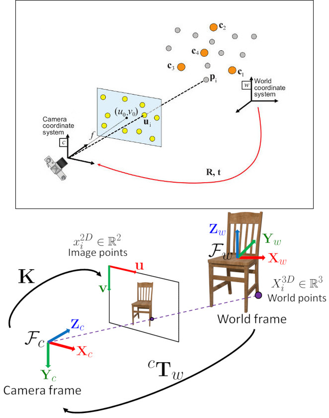
問題の定式化: ワールド基準座標系で表された3D点 \(p_i\) と、それらの画像上への2D投影 \(u_i\) の対応の組が与えられたとき、ワールドに対するカメラの姿勢( \(R\) と \(t\) )および焦点距離 \(f\) を求めることを目指す。

OpenCVはPerspective-*n*-Point問題を解くための4つの異なるアプローチを提供しており、それらは \(R\) と \(t\) を返す。その後、以下の式を用いて3D点を画像平面へ投影できる。

\[s\ \left [ \begin{matrix} u \\ v \\ 1 \end{matrix} \right ] = \left [ \begin{matrix} f_x & 0 & c_x \\ 0 & f_y & c_y \\ 0 & 0 & 1 \end{matrix} \right ] \left [ \begin{matrix} r_{11} & r_{12} & r_{13} & t_1 \\ r_{21} & r_{22} & r_{23} & t_2 \\ r_{31} & r_{32} & r_{33} & t_3 \end{matrix} \right ] \left [ \begin{matrix} X \\ Y \\ Z\\ 1 \end{matrix} \right ]\]

これらの式の扱い方に関する完全なドキュメントは カメラキャリブレーションと3D再構成 にある。

ソースコード

このチュートリアルのソースコードは、OpenCVソースライブラリの samples/cpp/tutorial_code/calib3d/real_time_pose_estimation/ フォルダにある。

このチュートリアルは2つの主要なプログラムから構成される。

  1. モデル登録

    このアプリケーションは、検出対象の物体のテクスチャ付き3Dモデルを持っていないユーザー向けである。このプログラムを使って独自のテクスチャ付き3Dモデルを作成できる。このプログラムは平面物体に対してのみ動作するため、複雑な形状の物体をモデル化したい場合は、高度なソフトウェアを使って作成すべきである。

    このアプリケーションは、登録する物体の入力画像とその3Dメッシュを必要とする。さらに、入力画像が撮影されたカメラの内部パラメータも与える必要がある。すべてのファイルは、絶対パス、またはアプリケーションの作業ディレクトリからの相対パスで指定する必要がある。ファイルが指定されない場合、プログラムは用意されたデフォルトパラメータを開こうとする。

    このアプリケーションは、入力画像からORB特徴と記述子を抽出するところから始まり、次にメッシュと Möller–Trumbore交差判定アルゴリズム を用いて、見つかった特徴の3D座標を計算する。最後に、3D点と記述子はYAML形式のファイル内の異なるリストに格納され、各行が異なる点となる。ファイルの格納方法に関する技術的背景は、XML / YAML / JSONファイルを用いたファイル入出力 チュートリアルにある。

  1. モデル検出

    このアプリケーションの目的は、物体のテクスチャ付き3Dモデルが与えられたときに、その物体姿勢をリアルタイムで推定することである。

    このアプリケーションは、モデル登録プログラムで説明したものと同じ構造を持つYAMLファイル形式のテクスチャ付き3Dモデルを読み込むところから始まる。シーンからORB特徴と記述子が検出・抽出される。次に、シーン記述子とモデル記述子のマッチングを行うために、cv::flann::GenericIndex を伴う cv::FlannBasedMatcher が使われる。見つかったマッチと cv::solvePnPRansac 関数を用いて、カメラの Rt が計算される。最後に、不正な姿勢を棄却するためにKalmanFilterが適用される。

    OpenCVをサンプル付きでコンパイルした場合、opencv/build/bin/cpp-tutorial-pnp_detection‘ にそれを見つけることができる。そして、アプリケーションを実行していくつかのパラメータを変更できる。

    This program shows how to detect an object given its 3D textured model. You can choose to use a recorded video or the webcam.
    Usage:
    ./cpp-tutorial-pnp_detection -help
    Keys:
    'esc’ - to quit.
    -----------------------------------------------------------------------—
    Usage: cpp-tutorial-pnp_detection [params]
    -c, –confidence (value:0.95)
    RANSAC confidence
    -e, –error (value:2.0)
    RANSAC reprojection error
    -f, –fast (value:true)
    use of robust fast match
    -h, –help (value:true)
    print this message
    –in, –inliers (value:30)
    minimum inliers for Kalman update
    –it, –iterations (value:500)
    RANSAC maximum iterations count
    -k, –keypoints (value:2000)
    number of keypoints to detect
    –mesh
    path to ply mesh
    –method, –pnp (value:0)
    PnP method: (0) ITERATIVE - (1) EPNP - (2) P3P - (3) DLS
    –model
    path to yml model
    -r, –ratio (value:0.7)
    threshold for ratio test
    -v, –video
    path to recorded video

    たとえば、pnpメソッドを変更してアプリケーションを実行できる。

    ./cpp-tutorial-pnp_detection --method=2

解説

ここでは、リアルタイムアプリケーションのコードを詳細に説明する。

  1. テクスチャ付き3D物体モデルと物体メッシュを読み込む。

    テクスチャ付きモデルを読み込むために、YAMLファイルを開いて格納された3D点とそれに対応する記述子を取得する関数 load() を持つ クラス Model を実装した。テクスチャ付き3Dモデルの例は samples/cpp/tutorial_code/calib3d/real_time_pose_estimation/Data/cookies_ORB.yml にある。

    /* Load a YAML file using OpenCV */
    void Model::load(const std::string path)
    {
    cv::Mat points3d_mat;
    storage["points_3d"] >> points3d_mat;
    storage["descriptors"] >> descriptors_;
    points3d_mat.copyTo(list_points3d_in_);
    storage.release();
    }
    XML/YAML/JSON file storage class that encapsulates all the information necessary for writing or readi...
    Definition persistence.hpp:261
    @ READ
    value, open the file for reading
    Definition persistence.hpp:266
    n-dimensional dense array class
    Definition mat.hpp:840
    void copyTo(OutputArray m) const
    Copies the matrix to another one.

    メインプログラムでは、モデルは次のように読み込まれる。

    Model model; // instantiate Model object
    model.load(yml_read_path); // load a 3D textured object model

    モデルメッシュを読み込むために、\(*\).ply ファイルを開いて物体の3D点および構成する三角形を格納する関数 load() を持つ クラス Mesh を実装した。モデルメッシュの例は samples/cpp/tutorial_code/calib3d/real_time_pose_estimation/Data/box.ply にある。

    /* Load a CSV with *.ply format */
    void Mesh::load(const std::string path)
    {
    // Create the reader
    CsvReader csvReader(path);
    // Clear previous data
    list_vertex_.clear();
    list_triangles_.clear();
    // Read from .ply file
    csvReader.readPLY(list_vertex_, list_triangles_);
    // Update mesh attributes
    num_vertexs_ = list_vertex_.size();
    num_triangles_ = list_triangles_.size();
    }

    メインプログラムでは、メッシュは次のように読み込まれる。

    Mesh mesh; // instantiate Mesh object
    mesh.load(ply_read_path); // load an object mesh

    別のモデルやメッシュを読み込むこともできる。

    ./cpp-tutorial-pnp_detection --mesh=/absolute_path_to_your_mesh.ply --model=/absolute_path_to_your_model.yml
  2. カメラまたはビデオから入力を取得する

    検出するにはビデオをキャプチャする必要がある。これは、マシン上のビデオが置かれている絶対パスを渡して録画済みビデオを読み込むことで行う。アプリケーションをテストするには、samples/cpp/tutorial_code/calib3d/real_time_pose_estimation/Data/box.mp4 に録画済みビデオがある。

    cv::VideoCapture cap; // instantiate VideoCapture
    cap.open(video_read_path); // open a recorded video
    if(!cap.isOpened()) // check if we succeeded
    {
    std::cout << "Could not open the camera device" << std::endl;
    return -1;
    }
    Class for video capturing from video files, image sequences or cameras.
    Definition videoio.hpp:786
    virtual bool open(const String &filename, int apiPreference=CAP_ANY)
    Opens a video file or a capturing device or an IP video stream for video capturing.
    virtual bool isOpened() const
    Returns true if video capturing has been initialized already.

    そしてアルゴリズムはフレームごとに計算される。

    cv::Mat frame, frame_vis;
    while(cap.read(frame) && cv::waitKey(30) != 27) // capture frame until ESC is pressed
    {
    frame_vis = frame.clone(); // refresh visualisation frame
    // MAIN ALGORITHM
    }
    CV_NODISCARD_STD Mat clone() const
    Creates a full copy of the array and the underlying data.
    virtual bool read(OutputArray image)
    Grabs, decodes and returns the next video frame.
    int waitKey(int delay=0)
    Waits for a pressed key.

    別の録画済みビデオを読み込むこともできる。

    ./cpp-tutorial-pnp_detection --video=/absolute_path_to_your_video.mp4
  3. シーンからORB特徴と記述子を抽出する

    次のステップは、シーンの特徴を検出してその記述子を抽出することである。このタスクのために、キーポイント検出と特徴抽出のための関数を持つ クラス RobustMatcher を実装した。これは samples/cpp/tutorial_code/calib3d/real_time_pose_estimation/src/RobusMatcher.cpp にある。RobusMatch オブジェクトでは、OpenCVの2D特徴検出器のいずれも使用できる。今回は cv::ORB 特徴を使った。なぜなら、キーポイントの検出に cv::FAST を、記述子の抽出に cv::xfeatures2d::BriefDescriptorExtractor を基にしており、高速で回転に対してロバストだからである。ORB に関するより詳細な情報はドキュメントにある。

    以下のコードは、特徴検出器と記述子抽出器をインスタンス化して設定する方法である。

    RobustMatcher rmatcher; // instantiate RobustMatcher
    cv::FeatureDetector * detector = new cv::OrbFeatureDetector(numKeyPoints); // instantiate ORB feature detector
    cv::DescriptorExtractor * extractor = new cv::OrbDescriptorExtractor(); // instantiate ORB descriptor extractor
    rmatcher.setFeatureDetector(detector); // set feature detector
    rmatcher.setDescriptorExtractor(extractor); // set descriptor extractor
    Abstract base class for 2D image feature detectors and descriptor extractors.
    Definition features2d.hpp:139

    特徴と記述子は、マッチング関数の内部で RobustMatcher によって計算される。

  4. Flannマッチャを使ってシーン記述子をモデル記述子とマッチングする

    これは検出アルゴリズムの最初のステップである。主なアイデアは、現在のシーン内で見つかった特徴の3D座標を知るために、シーン記述子をモデル記述子とマッチングすることである。

    まず、どのマッチャを使用するかを設定する必要がある。今回は cv::FlannBasedMatcher マッチャを使う。これは、学習済みの特徴コレクションが増えるにつれて、計算コストの面で cv::BFMatcher マッチャより高速である。そして、FlannBasedマッチャでは、ORB 記述子がバイナリであるため、作成されるインデックスは Multi-Probe LSH: Efficient Indexing for High-Dimensional Similarity Search となる。

    LSH と探索パラメータを調整して、マッチングの効率を改善できる。

    cv::Ptr<cv::flann::IndexParams> indexParams = cv::makePtr<cv::flann::LshIndexParams>(6, 12, 1); // instantiate LSH index parameters
    cv::Ptr<cv::flann::SearchParams> searchParams = cv::makePtr<cv::flann::SearchParams>(50); // instantiate flann search parameters
    cv::DescriptorMatcher * matcher = new cv::FlannBasedMatcher(indexParams, searchParams); // instantiate FlannBased matcher
    rmatcher.setDescriptorMatcher(matcher); // set matcher
    Abstract base class for matching keypoint descriptors.
    Definition features2d.hpp:1004
    Flann-based descriptor matcher.
    Definition features2d.hpp:1303
    std::shared_ptr< _Tp > Ptr
    Definition cvstd_wrapper.hpp:23
    static Ptr< _Tp > makePtr(const A1 &... a1)
    Definition cvstd_wrapper.hpp:26

    次に、robustMatch() または fastRobustMatch() 関数を使ってマッチャを呼び出す必要がある。この2つの関数を使う違いはその計算コストである。最初のメソッドは遅いが、2つの比率テストと対称性テストを使うため、良いマッチをフィルタリングする上でよりロバストである。対照的に、2番目のメソッドは高速だが、マッチに対して単一の比率テストしか適用しないためロバスト性は低い。

    以下のコードは、モデルの3D点とその記述子を取得し、メインプログラムでマッチャを呼び出すものである。

    // Get the MODEL INFO
    std::vector<cv::Point3f> list_points3d_model = model.get_points3d(); // list with model 3D coordinates
    cv::Mat descriptors_model = model.get_descriptors(); // list with descriptors of each 3D coordinate
    // -- Step 1: Robust matching between model descriptors and scene descriptors
    std::vector<cv::DMatch> good_matches; // to obtain the model 3D points in the scene
    std::vector<cv::KeyPoint> keypoints_scene; // to obtain the 2D points of the scene
    if(fast_match)
    {
    rmatcher.fastRobustMatch(frame, good_matches, keypoints_scene, descriptors_model);
    }
    else
    {
    rmatcher.robustMatch(frame, good_matches, keypoints_scene, descriptors_model);
    }

    以下のコードは、RobustMatcher クラスに属する robustMatch() 関数に対応する。この関数は、与えられた画像を使ってキーポイントを検出して記述子を抽出し、抽出した記述子と与えられたモデル記述子を 2近傍(two Nearest Neighbour) を使って双方向にマッチングする。そして、最良マッチと2番目に良いマッチの距離比が与えられたしきい値より大きいマッチを除去するために、両方向のマッチに比率テストを適用する。最後に、非対称なマッチを除去するために対称性テストを適用する。

    void RobustMatcher::robustMatch( const cv::Mat& frame, std::vector<cv::DMatch>& good_matches,
    std::vector<cv::KeyPoint>& keypoints_frame,
    const std::vector<cv::KeyPoint>& keypoints_model, const cv::Mat& descriptors_model )
    {
    // 1a. Detection of the ORB features
    this->computeKeyPoints(frame, keypoints_frame);
    // 1b. Extraction of the ORB descriptors
    cv::Mat descriptors_frame;
    this->computeDescriptors(frame, keypoints_frame, descriptors_frame);
    // 2. Match the two image descriptors
    std::vector<std::vector<cv::DMatch> > matches12, matches21;
    // 2a. From image 1 to image 2
    matcher_->knnMatch(descriptors_frame, descriptors_model, matches12, 2); // return 2 nearest neighbours
    // 2b. From image 2 to image 1
    matcher_->knnMatch(descriptors_model, descriptors_frame, matches21, 2); // return 2 nearest neighbours
    // 3. Remove matches for which NN ratio is > than threshold
    // clean image 1 -> image 2 matches
    int removed1 = ratioTest(matches12);
    // clean image 2 -> image 1 matches
    int removed2 = ratioTest(matches21);
    // 4. Remove non-symmetrical matches
    symmetryTest(matches12, matches21, good_matches);
    }

    マッチのフィルタリング後、得られた DMatches ベクトルを使って、見つかったシーンキーポイントと3Dモデルから2Dと3Dの対応を抽出する必要がある。cv::DMatch に関するより詳しい情報はドキュメントを参照のこと。

    // -- Step 2: Find out the 2D/3D correspondences
    std::vector<cv::Point3f> list_points3d_model_match; // container for the model 3D coordinates found in the scene
    std::vector<cv::Point2f> list_points2d_scene_match; // container for the model 2D coordinates found in the scene
    for(unsigned int match_index = 0; match_index < good_matches.size(); ++match_index)
    {
    cv::Point3f point3d_model = list_points3d_model[ good_matches[match_index].trainIdx ]; // 3D point from model
    cv::Point2f point2d_scene = keypoints_scene[ good_matches[match_index].queryIdx ].pt; // 2D point from the scene
    list_points3d_model_match.push_back(point3d_model); // add 3D point
    list_points2d_scene_match.push_back(point2d_scene); // add 2D point
    }
    Template class for 3D points specified by its coordinates x, y and z.
    Definition types.hpp:255

    比率テストのしきい値や検出するキーポイント数を変更したり、ロバストマッチャを使うかどうかを変更したりすることもできる。

    ./cpp-tutorial-pnp_detection --ratio=0.8 --keypoints=1000 --fast=false
  5. PnP + Ransacによる姿勢推定

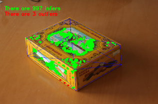
    2Dと3Dの対応が得られたら、カメラ姿勢を推定するためにPnPアルゴリズムを適用する必要がある。cv::solvePnP ではなく cv::solvePnPRansac を使わなければならない理由は、マッチング後に見つかった対応がすべて正しいわけではなく、おそらく誤った対応、すなわち 外れ値(outliers) が存在するという事実による。Random Sample Consensus すなわち Ransac は、観測データから数学的モデルのパラメータを推定する非決定的な反復手法であり、反復回数が増えるにつれて近似的な結果を生成する。Ransac を適用した後、すべての 外れ値(outliers) が除去され、その後、良い解を得る一定の確率でカメラ姿勢を推定する。

    カメラ姿勢推定のために、クラス PnPProblem を実装した。この クラス は4つの属性を持つ。すなわち、与えられたキャリブレーション行列、回転行列、並進行列、回転並進行列である。姿勢推定に使用しているカメラの内部キャリブレーションパラメータが必要である。これらのパラメータを得るには、正方チェスボードによるカメラキャリブレーションOpenCVによるカメラキャリブレーション のチュートリアルを確認できる。

    以下のコードは、メインプログラムで PnPProblemクラス を宣言する方法である。

    // Intrinsic camera parameters: UVC WEBCAM
    double f = 55; // focal length in mm
    double sx = 22.3, sy = 14.9; // sensor size
    double width = 640, height = 480; // image size
    double params_WEBCAM[] = { width*f/sx, // fx
    height*f/sy, // fy
    width/2, // cx
    height/2}; // cy
    PnPProblem pnp_detection(params_WEBCAM); // instantiate PnPProblem class

    以下のコードは、PnPProblemクラス がその属性を初期化する方法である。

    // Custom constructor given the intrinsic camera parameters
    PnPProblem::PnPProblem(const double params[])
    {
    _A_matrix = cv::Mat::zeros(3, 3, CV_64FC1); // intrinsic camera parameters
    _A_matrix.at<double>(0, 0) = params[0]; // [ fx 0 cx ]
    _A_matrix.at<double>(1, 1) = params[1]; // [ 0 fy cy ]
    _A_matrix.at<double>(0, 2) = params[2]; // [ 0 0 1 ]
    _A_matrix.at<double>(1, 2) = params[3];
    _A_matrix.at<double>(2, 2) = 1;
    _R_matrix = cv::Mat::zeros(3, 3, CV_64FC1); // rotation matrix
    _t_matrix = cv::Mat::zeros(3, 1, CV_64FC1); // translation matrix
    _P_matrix = cv::Mat::zeros(3, 4, CV_64FC1); // rotation-translation matrix
    }
    static CV_NODISCARD_STD MatExpr zeros(int rows, int cols, int type)
    Returns a zero array of the specified size and type.
    #define CV_64FC1
    Definition interface.h:124

    OpenCVは4つのPnPメソッド、ITERATIVE、EPNP、P3P、DLSを提供する。アプリケーションの種類に応じて推定メソッドは異なる。リアルタイムアプリケーションを作りたい場合は、最適解を見つける際にITERATIVEやDLSより高速であるため、EPNPとP3Pがより適している。しかし、EPNPとP3Pは平面に対して特にロバストというわけではなく、姿勢推定が鏡像効果を持つように見えることがある。したがって、このチュートリアルでは、検出対象の物体が平面を持つため、ITERATIVEメソッドが使われる。

    OpenCVのRANSAC実装では、3つのパラメータを与える必要がある。1) アルゴリズムが停止するまでの最大反復回数、2) 観測された点投影と計算された点投影との間で、それをインライアとみなすために許容される最大距離、3) 良い結果を得るための信頼度である。アルゴリズムの性能を向上させるために、これらのパラメータを調整できる。反復回数を増やすとより正確な解が得られるが、解を見つけるのに時間がかかる。再投影誤差を増やすと計算時間は減るが、解は不正確になる。信頼度を下げるとアルゴリズムは高速になるが、得られる解は不正確になる。

    以下のパラメータがこのアプリケーションで機能する。

    // RANSAC parameters
    int iterationsCount = 500; // number of Ransac iterations.
    float reprojectionError = 2.0; // maximum allowed distance to consider it an inlier.
    float confidence = 0.95; // RANSAC successful confidence.

    以下のコードは、PnPProblemクラス に属する estimatePoseRANSAC() 関数に対応する。この関数は、2D/3D対応の組、使用する所望のPnPメソッド、出力インライアコンテナ、Ransacパラメータが与えられたときに、回転行列と並進行列を推定する。

    // Estimate the pose given a list of 2D/3D correspondences with RANSAC and the method to use
    void PnPProblem::estimatePoseRANSAC( const std::vector<cv::Point3f> &list_points3d, // list with model 3D coordinates
    const std::vector<cv::Point2f> &list_points2d, // list with scene 2D coordinates
    int flags, cv::Mat &inliers, int iterationsCount, // PnP method; inliers container
    float reprojectionError, float confidence ) // RANSAC parameters
    {
    cv::Mat distCoeffs = cv::Mat::zeros(4, 1, CV_64FC1); // vector of distortion coefficients
    cv::Mat rvec = cv::Mat::zeros(3, 1, CV_64FC1); // output rotation vector
    cv::Mat tvec = cv::Mat::zeros(3, 1, CV_64FC1); // output translation vector
    bool useExtrinsicGuess = false; // if true the function uses the provided rvec and tvec values as
    // initial approximations of the rotation and translation vectors
    cv::solvePnPRansac( list_points3d, list_points2d, _A_matrix, distCoeffs, rvec, tvec,
    useExtrinsicGuess, iterationsCount, reprojectionError, confidence,
    inliers, flags );
    Rodrigues(rvec,_R_matrix); // converts Rotation Vector to Matrix
    _t_matrix = tvec; // set translation matrix
    this->set_P_matrix(_R_matrix, _t_matrix); // set rotation-translation matrix
    }
    bool solvePnPRansac(InputArray objectPoints, InputArray imagePoints, InputArray cameraMatrix, InputArray distCoeffs, OutputArray rvec, OutputArray tvec, bool useExtrinsicGuess=false, int iterationsCount=100, float reprojectionError=8.0, double confidence=0.99, OutputArray inliers=noArray(), int flags=SOLVEPNP_ITERATIVE)
    Finds an object pose from 3D-2D point correspondences using the RANSAC scheme to deal with bad match...

    以下のコードは、メインアルゴリズムの3番目と4番目のステップである。1つ目は上記の関数を呼び出すこと、2つ目はRANSACからの出力インライアベクトルを取得して、描画目的のために2Dシーン点を得ることである。コードに見られるように、マッチがある場合にRANSACを適用するよう注意しなければならない。そうでない場合、OpenCVの何らかの バグ により cv::solvePnPRansac 関数がクラッシュする。

    if(good_matches.size() > 0) // None matches, then RANSAC crashes
    {
    // -- Step 3: Estimate the pose using RANSAC approach
    pnp_detection.estimatePoseRANSAC( list_points3d_model_match, list_points2d_scene_match,
    pnpMethod, inliers_idx, iterationsCount, reprojectionError, confidence );
    // -- Step 4: Catch the inliers keypoints to draw
    for(int inliers_index = 0; inliers_index < inliers_idx.rows; ++inliers_index)
    {
    int n = inliers_idx.at<int>(inliers_index); // i-inlier
    cv::Point2f point2d = list_points2d_scene_match[n]; // i-inlier point 2D
    list_points2d_inliers.push_back(point2d); // add i-inlier to list
    }

    最後に、カメラ姿勢が推定されたら、理論 で示した式を用いて、ワールド基準座標系で表された与えられた3D点の画像上への2D投影を計算するために \(R\) と \(t\) を使用できる。

    以下のコードは、PnPProblemクラス に属する backproject3DPoint() 関数に対応する。この関数は、ワールド基準座標系で表された与えられた3D点を2D画像上へ逆投影する。

    // Backproject a 3D point to 2D using the estimated pose parameters
    cv::Point2f PnPProblem::backproject3DPoint(const cv::Point3f &point3d)
    {
    // 3D point vector [x y z 1]'
    cv::Mat point3d_vec = cv::Mat(4, 1, CV_64FC1);
    point3d_vec.at<double>(0) = point3d.x;
    point3d_vec.at<double>(1) = point3d.y;
    point3d_vec.at<double>(2) = point3d.z;
    point3d_vec.at<double>(3) = 1;
    // 2D point vector [u v 1]'
    cv::Mat point2d_vec = cv::Mat(4, 1, CV_64FC1);
    point2d_vec = _A_matrix * _P_matrix * point3d_vec;
    // Normalization of [u v]'
    cv::Point2f point2d;
    point2d.x = point2d_vec.at<double>(0) / point2d_vec.at<double>(2);
    point2d.y = point2d_vec.at<double>(1) / point2d_vec.at<double>(2);
    return point2d;
    }
    _Tp & at(int i0=0)
    Returns a reference to the specified array element.
    _Tp x
    x coordinate of the 3D point
    Definition types.hpp:284
    _Tp y
    y coordinate of the point
    Definition types.hpp:202
    _Tp x
    x coordinate of the point
    Definition types.hpp:201

    上記の関数は、物体の姿勢を表示するために物体 Mesh のすべての3D点を計算するのに使われる。

    RANSACパラメータやPnPメソッドを変更することもできる。

    ./cpp-tutorial-pnp_detection --error=0.25 --confidence=0.90 --iterations=250 --method=3
  6. 不正な姿勢を棄却するための線形カルマンフィルタ

    コンピュータビジョンやロボティクス分野では、検出や追跡の手法を適用した後、何らかのセンサ誤差により悪い結果が得られることはよくある。これらの不正な検出を避けるために、このチュートリアルでは線形カルマンフィルタの実装方法を説明する。カルマンフィルタは、与えられた数のインライアが検出された後に適用される。

    カルマンフィルタ が何であるかについては、より詳しい情報を見つけることができる。このチュートリアルでは、ダイナミクスモデルと観測モデルを設定するために、位置と姿勢の追跡のための線形カルマンフィルタ に基づくOpenCV実装の cv::KalmanFilter を使用する。

    まず、18個の状態を持つ状態ベクトルを定義する必要がある。位置データ (x,y,z) とその1次および2次導関数(速度と加速度)、次に3つのオイラー角(ロール、ピッチ、ヨー)の形で回転が追加され、それらの1次および2次導関数(角速度と角加速度)が加わる。

    \[X = (x,y,z,\dot x,\dot y,\dot z,\ddot x,\ddot y,\ddot z,\psi,\theta,\phi,\dot \psi,\dot \theta,\dot \phi,\ddot \psi,\ddot \theta,\ddot \phi)^T\]

    次に、観測数を定義する必要がある。これは6となる。すなわち \(R\) と \(t\) から \((x,y,z)\) と \((\psi,\theta,\phi)\) を取り出せる。さらに、システムに適用する制御入力の数を定義する必要があるが、この場合はゼロとなる。最後に、観測間の差分時間を定義する必要があり、この場合は \(1/T\) である。ここで T は動画のフレームレートである。

    cv::KalmanFilter KF; // instantiate Kalman Filter
    int nStates = 18; // the number of states
    int nMeasurements = 6; // the number of measured states
    int nInputs = 0; // the number of action control
    double dt = 0.125; // time between measurements (1/FPS)
    initKalmanFilter(KF, nStates, nMeasurements, nInputs, dt); // init function
    Kalman filter class.
    Definition tracking.hpp:435

    以下のコードはカルマンフィルタの初期化に対応する。まず、プロセスノイズ、観測ノイズ、誤差共分散行列を設定する。次に、動的モデルである遷移行列を設定し、最後に観測モデルである観測行列を設定する。

    プロセスノイズと観測ノイズを調整してカルマンフィルタの性能を向上させることができる。観測ノイズを小さくするほど収束は速くなるが、その分アルゴリズムは不良な観測に対して敏感になる。

    void initKalmanFilter(cv::KalmanFilter &KF, int nStates, int nMeasurements, int nInputs, double dt)
    {
    KF.init(nStates, nMeasurements, nInputs, CV_64F); // init Kalman Filter
    cv::setIdentity(KF.processNoiseCov, cv::Scalar::all(1e-5)); // set process noise
    cv::setIdentity(KF.measurementNoiseCov, cv::Scalar::all(1e-4)); // set measurement noise
    cv::setIdentity(KF.errorCovPost, cv::Scalar::all(1)); // error covariance
    /* DYNAMIC MODEL */
    // [1 0 0 dt 0 0 dt2 0 0 0 0 0 0 0 0 0 0 0]
    // [0 1 0 0 dt 0 0 dt2 0 0 0 0 0 0 0 0 0 0]
    // [0 0 1 0 0 dt 0 0 dt2 0 0 0 0 0 0 0 0 0]
    // [0 0 0 1 0 0 dt 0 0 0 0 0 0 0 0 0 0 0]
    // [0 0 0 0 1 0 0 dt 0 0 0 0 0 0 0 0 0 0]
    // [0 0 0 0 0 1 0 0 dt 0 0 0 0 0 0 0 0 0]
    // [0 0 0 0 0 0 1 0 0 0 0 0 0 0 0 0 0 0]
    // [0 0 0 0 0 0 0 1 0 0 0 0 0 0 0 0 0 0]
    // [0 0 0 0 0 0 0 0 1 0 0 0 0 0 0 0 0 0]
    // [0 0 0 0 0 0 0 0 0 1 0 0 dt 0 0 dt2 0 0]
    // [0 0 0 0 0 0 0 0 0 0 1 0 0 dt 0 0 dt2 0]
    // [0 0 0 0 0 0 0 0 0 0 0 1 0 0 dt 0 0 dt2]
    // [0 0 0 0 0 0 0 0 0 0 0 0 1 0 0 dt 0 0]
    // [0 0 0 0 0 0 0 0 0 0 0 0 0 1 0 0 dt 0]
    // [0 0 0 0 0 0 0 0 0 0 0 0 0 0 1 0 0 dt]
    // [0 0 0 0 0 0 0 0 0 0 0 0 0 0 0 1 0 0]
    // [0 0 0 0 0 0 0 0 0 0 0 0 0 0 0 0 1 0]
    // [0 0 0 0 0 0 0 0 0 0 0 0 0 0 0 0 0 1]
    // position
    KF.transitionMatrix.at<double>(0,3) = dt;
    KF.transitionMatrix.at<double>(1,4) = dt;
    KF.transitionMatrix.at<double>(2,5) = dt;
    KF.transitionMatrix.at<double>(3,6) = dt;
    KF.transitionMatrix.at<double>(4,7) = dt;
    KF.transitionMatrix.at<double>(5,8) = dt;
    KF.transitionMatrix.at<double>(0,6) = 0.5*pow(dt,2);
    KF.transitionMatrix.at<double>(1,7) = 0.5*pow(dt,2);
    KF.transitionMatrix.at<double>(2,8) = 0.5*pow(dt,2);
    // orientation
    KF.transitionMatrix.at<double>(9,12) = dt;
    KF.transitionMatrix.at<double>(10,13) = dt;
    KF.transitionMatrix.at<double>(11,14) = dt;
    KF.transitionMatrix.at<double>(12,15) = dt;
    KF.transitionMatrix.at<double>(13,16) = dt;
    KF.transitionMatrix.at<double>(14,17) = dt;
    KF.transitionMatrix.at<double>(9,15) = 0.5*pow(dt,2);
    KF.transitionMatrix.at<double>(10,16) = 0.5*pow(dt,2);
    KF.transitionMatrix.at<double>(11,17) = 0.5*pow(dt,2);
    /* MEASUREMENT MODEL */
    // [1 0 0 0 0 0 0 0 0 0 0 0 0 0 0 0 0 0]
    // [0 1 0 0 0 0 0 0 0 0 0 0 0 0 0 0 0 0]
    // [0 0 1 0 0 0 0 0 0 0 0 0 0 0 0 0 0 0]
    // [0 0 0 0 0 0 0 0 0 1 0 0 0 0 0 0 0 0]
    // [0 0 0 0 0 0 0 0 0 0 1 0 0 0 0 0 0 0]
    // [0 0 0 0 0 0 0 0 0 0 0 1 0 0 0 0 0 0]
    KF.measurementMatrix.at<double>(0,0) = 1; // x
    KF.measurementMatrix.at<double>(1,1) = 1; // y
    KF.measurementMatrix.at<double>(2,2) = 1; // z
    KF.measurementMatrix.at<double>(3,9) = 1; // roll
    KF.measurementMatrix.at<double>(4,10) = 1; // pitch
    KF.measurementMatrix.at<double>(5,11) = 1; // yaw
    }
    Mat transitionMatrix
    state transition matrix (A)
    Definition tracking.hpp:469
    Mat measurementMatrix
    measurement matrix (H)
    Definition tracking.hpp:471
    Mat errorCovPost
    posteriori error estimate covariance matrix (P(k)): P(k)=(I-K(k)*H)*P'(k)
    Definition tracking.hpp:476
    void init(int dynamParams, int measureParams, int controlParams=0, int type=CV_32F)
    Re-initializes Kalman filter. The previous content is destroyed.
    Mat measurementNoiseCov
    measurement noise covariance matrix (R)
    Definition tracking.hpp:473
    Mat processNoiseCov
    process noise covariance matrix (Q)
    Definition tracking.hpp:472
    static Scalar_< double > all(double v0)
    void setIdentity(InputOutputArray mtx, const Scalar &s=Scalar(1))
    Initializes a scaled identity matrix.
    #define CV_64F
    Definition interface.h:79

    以下のコードはメインアルゴリズムの第5ステップである。Ransac後に得られたインライア数がしきい値を超えたとき、観測行列が埋められ、続いてカルマンフィルタが更新される:

    // -- Step 5: Kalman Filter
    // GOOD MEASUREMENT
    if( inliers_idx.rows >= minInliersKalman )
    {
    // Get the measured translation
    cv::Mat translation_measured(3, 1, CV_64F);
    translation_measured = pnp_detection.get_t_matrix();
    // Get the measured rotation
    cv::Mat rotation_measured(3, 3, CV_64F);
    rotation_measured = pnp_detection.get_R_matrix();
    // fill the measurements vector
    fillMeasurements(measurements, translation_measured, rotation_measured);
    }
    // Instantiate estimated translation and rotation
    cv::Mat translation_estimated(3, 1, CV_64F);
    cv::Mat rotation_estimated(3, 3, CV_64F);
    // update the Kalman filter with good measurements
    updateKalmanFilter( KF, measurements,
    translation_estimated, rotation_estimated);

    以下のコードはfillMeasurements()関数に対応する。この関数は、観測された回転行列をオイラー角に変換し、観測された並進ベクトルとともに観測行列を埋める:

    void fillMeasurements( cv::Mat &measurements,
    const cv::Mat &translation_measured, const cv::Mat &rotation_measured)
    {
    // Convert rotation matrix to euler angles
    cv::Mat measured_eulers(3, 1, CV_64F);
    measured_eulers = rot2euler(rotation_measured);
    // Set measurement to predict
    measurements.at<double>(0) = translation_measured.at<double>(0); // x
    measurements.at<double>(1) = translation_measured.at<double>(1); // y
    measurements.at<double>(2) = translation_measured.at<double>(2); // z
    measurements.at<double>(3) = measured_eulers.at<double>(0); // roll
    measurements.at<double>(4) = measured_eulers.at<double>(1); // pitch
    measurements.at<double>(5) = measured_eulers.at<double>(2); // yaw
    }

    以下のコードはupdateKalmanFilter()関数に対応する。この関数はカルマンフィルタを更新し、推定された回転行列と並進ベクトルを設定する。推定された回転行列は、推定されたオイラー角から回転行列へ変換することで得られる。

    void updateKalmanFilter( cv::KalmanFilter &KF, cv::Mat &measurement,
    cv::Mat &translation_estimated, cv::Mat &rotation_estimated )
    {
    // First predict, to update the internal statePre variable
    cv::Mat prediction = KF.predict();
    // The "correct" phase that is going to use the predicted value and our measurement
    cv::Mat estimated = KF.correct(measurement);
    // Estimated translation
    translation_estimated.at<double>(0) = estimated.at<double>(0);
    translation_estimated.at<double>(1) = estimated.at<double>(1);
    translation_estimated.at<double>(2) = estimated.at<double>(2);
    // Estimated euler angles
    cv::Mat eulers_estimated(3, 1, CV_64F);
    eulers_estimated.at<double>(0) = estimated.at<double>(9);
    eulers_estimated.at<double>(1) = estimated.at<double>(10);
    eulers_estimated.at<double>(2) = estimated.at<double>(11);
    // Convert estimated quaternion to rotation matrix
    rotation_estimated = euler2rot(eulers_estimated);
    }
    const Mat & correct(const Mat &measurement)
    Updates the predicted state from the measurement.
    const Mat & predict(const Mat &control=Mat())
    Computes a predicted state.

    第6ステップは、推定された回転・並進行列を設定することである:

    // -- Step 6: Set estimated projection matrix
    pnp_detection_est.set_P_matrix(rotation_estimated, translation_estimated);

    最後の省略可能なステップは、求めた姿勢を描画することである。これを行うために、メッシュの3D点をすべて描画し、さらに参照座標軸を描画する関数を実装した:

    // -- Step X: Draw pose
    drawObjectMesh(frame_vis, &mesh, &pnp_detection, green); // draw current pose
    drawObjectMesh(frame_vis, &mesh, &pnp_detection_est, yellow); // draw estimated pose
    double l = 5;
    std::vector<cv::Point2f> pose_points2d;
    pose_points2d.push_back(pnp_detection_est.backproject3DPoint(cv::Point3f(0,0,0))); // axis center
    pose_points2d.push_back(pnp_detection_est.backproject3DPoint(cv::Point3f(l,0,0))); // axis x
    pose_points2d.push_back(pnp_detection_est.backproject3DPoint(cv::Point3f(0,l,0))); // axis y
    pose_points2d.push_back(pnp_detection_est.backproject3DPoint(cv::Point3f(0,0,l))); // axis z
    draw3DCoordinateAxes(frame_vis, pose_points2d); // draw axes

    カルマンフィルタを更新するための最小インライア数を変更することもできる:

    ./cpp-tutorial-pnp_detection --inliers=20

結果

以下の動画は、説明した検出アルゴリズムを用いて以下の引数でリアルタイム姿勢推定を行った結果である:

// Robust Matcher parameters
int numKeyPoints = 2000; // number of detected keypoints
float ratio = 0.70f; // ratio test
bool fast_match = true; // fastRobustMatch() or robustMatch()
// RANSAC parameters
int iterationsCount = 500; // number of Ransac iterations.
int reprojectionError = 2.0; // maximum allowed distance to consider it an inlier.
float confidence = 0.95; // ransac successful confidence.
// Kalman Filter parameters
int minInliersKalman = 30; // Kalman threshold updating

リアルタイムの姿勢推定はこちらのYouTubeで視聴できる。